On this page
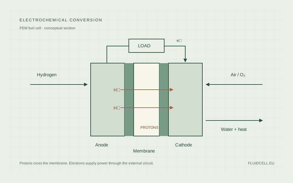
A proton exchange membrane (PEM) fuel cell converts hydrogen and oxygen into electrical energy, water and heat. Hydrogen enters the anode, oxygen is supplied to the cathode, and a polymer electrolyte conducts protons between them. Electrons travel through an external circuit, where their flow supplies electrical power. 1
Fuel must keep arriving for the cell to operate. A fuel cell does not store a fixed electrical charge in the way a battery does. Its performance depends on the hydrogen supply, air supply, temperature and water balance as well as the cell materials.
The reactions and the two current paths
At the anode, a catalyst promotes hydrogen oxidation:
H₂ → 2 H⁺ + 2 e⁻
The protons pass through the electrolyte. The electrons are conducted through the electrode and external circuit. At the cathode, oxygen reacts with arriving protons and electrons:
½ O₂ + 2 H⁺ + 2 e⁻ → H₂O
Adding the half-reactions gives H₂ + ½ O₂ → H₂O. The membrane separates the gas compartments and conducts ions while resisting electronic conduction. If electrons simply crossed through the electrolyte, their energy would bypass the external load. 3
In a hydrogen fuel cell generating power, the anode is the negative electrode and the cathode is positive. Electrode names refer to oxidation and reduction, so a PEM electrolyzer has different electrode polarity and operating chemistry. Fuel cells and electrolyzers should not be treated as interchangeable devices.
What is in the membrane electrode assembly?
The membrane electrode assembly, or MEA, contains the electrolyte membrane and catalyst layers on either side. In many practical assemblies, gas diffusion layers are also included in what a supplier calls the MEA; the exact scope of the term should be checked in the specification.
A catalyst layer needs paths for gas, electrons and protons. It typically contains catalyst particles, a conductive support and ionomer. A gas diffusion layer helps move gas toward the catalyst, carry current and manage water. Flow-field plates distribute reactants over the active area and provide electrical connections between cells.
Polymer electrolyte cells commonly use platinum or platinum-alloy catalysts. Their relatively low operating temperature and fuel sensitivity mean that hydrocarbons such as ethanol must first be processed into suitable hydrogen. A conventional PEM fuel cell cannot simply be fed raw ethanol as a substitute for hydrogen. 2
A stack connects many individual cells electrically in series. Stack voltage is the sum of cell voltages, but the current passes through every cell. A poorly supplied cell therefore affects the whole stack; stack-level averages can hide a local problem.
Why operating voltage falls under load
The reversible voltage is a thermodynamic limit for specified conditions. An operating cell has losses. Activation losses arise from the kinetics of the electrode reactions. Ohmic losses arise from resistance to ionic and electronic transport. At high current, concentration losses become more pronounced when reactants cannot reach reaction sites fast enough.
A polarization curve plots voltage against current density. It allows comparison at declared temperature, pressure, humidity and gas composition. A single maximum-power figure without those conditions gives little information about how the cell will behave in another system.
Electrical power is voltage multiplied by current. Increasing current does not increase power indefinitely because voltage falls, and the required air, hydrogen and cooling duties also change. System-control decisions must account for those additional loads. 5
Water is required, but excess water obstructs transport
Many low-temperature PEM membranes need hydration to conduct protons effectively. If the membrane dries out, its ionic resistance rises. Water is produced at the cathode, and water transport through the membrane and removal through the gas channels affect the cell's balance.
Excess liquid water can fill pores or obstruct flow channels, limiting gas access to the catalyst. This is often called flooding. A humidity setting that prevents drying at one load can cause flooding at another. Temperature, gas flow, pressure and humidification must therefore be controlled together. 5
Gas diffusion layers and channel geometry influence water removal. Startup, shutdown and cold conditions create different demands from steady warm operation. A well-performing MEA in a controlled test fixture does not prove that a stack has uniform humidity and temperature across its entire active area.
Work on zero-gradient test hardware explicitly controls gas composition, pressure, temperature and relative humidity to make material comparisons easier to interpret. The usefulness of such control also explains why small-cell results need care when applied to larger hardware. 6
Operating temperature depends on the membrane system
Conventional low-temperature PEM systems generally operate below water's normal boiling point, with the exact range determined by membrane chemistry, humidification and system design. DOE classifies polymer electrolyte cells as relatively low-temperature devices. Higher-temperature PEM variants use different electrolyte arrangements and require separate operating assumptions. 2
Higher temperature can help electrode kinetics and heat rejection, but can also change membrane hydration, material ageing and gas transport. A temperature quoted for one stack should not be copied into a specification for another.
Cooling is necessary because a portion of the fuel's energy becomes heat. In stationary combined heat and power equipment, some of that heat can be useful. The recoverable amount depends on temperature and the building's demand. Unused heat should not be counted as useful heat simply because it leaves the stack.
Stack efficiency and system efficiency
Stack efficiency compares the stack's direct-current electrical output with the energy in its hydrogen input. Net system efficiency also accounts for air supply, pumps, cooling, controls and power conversion. A reformer-fed installation has another boundary: the energy in the original fuel before hydrogen production.
DOE's technology comparison uses an LHV basis and distinguishes direct-hydrogen PEM performance from reformed-fuel performance. Those entries are comparative technology figures, not a promise for every commercial product. 4
A worked accounting example shows the difference. Suppose a stack produces 10 kW of DC power from 20 kW of hydrogen energy on an LHV basis. Its electrical efficiency is 50%. If auxiliaries and power conversion leave 8.8 kW available to the user, net electrical efficiency on the same fuel boundary is 44%. These are illustrative assumptions, not measured performance.
A combined heat and power efficiency adds useful recovered heat to net electrical output. It needs a defined heat-use condition. Comparing that combined figure with an electricity-only figure is misleading.
Fuel quality and degradation
Carbon monoxide can occupy catalyst sites and reduce hydrogen oxidation. Other impurities can damage components or change the water and gas environment. A fuel described as 99.99% hydrogen does not identify the remaining constituents. See hydrogen purity for PEM fuel cells for why contaminant-specific limits are necessary.
Durability also depends on operating history. Catalyst surface area can change, supports and membranes can degrade, and cycling can impose mechanical and chemical stresses. Material degradation and temporary losses from poor operating conditions are different causes of falling output; diagnosis needs more than a stack-voltage reading.
Record current, voltage, gas conditions, temperature and time when comparing durability results. Controlled test conditions help separate material changes from changes in humidity or reactant supply. 6
Where PEM cells are useful
Their response to changing loads and relatively low operating temperature make PEM cells useful in transport, backup power and some stationary systems. The complete installation still needs fuel delivery and controls. Battery buffers can handle short transients while a hydrogen system supplies longer-duration energy.
For a distributed installation, hydrogen availability and maintenance access can matter as much as nominal stack efficiency. A reformer brings catalyst and purification duties; an electrolyzer brings electricity and water-treatment requirements; delivered hydrogen brings transport and storage. The distributed production guide compares those system boundaries.
Sources & further reading
- Fuel cell basicsU.S. Department of Energy
- Types of fuel cellsU.S. Department of Energy
- Fuel cell animation: text versionU.S. Department of Energy
- Comparison of fuel cell technologiesU.S. Department of Energy · Reported efficiencies use the lower heating value (LHV) basis.
- Proton-Exchange Membrane Fuel Cell Balance of Plant and Performance Simulation for Vehicle Applications (2022)Energies, 15(21), 8110 · Open access, CC BY 4.0. Stack, air supply and thermal-system interactions.
- An open-source zero-gradient cell hardware to improve and accelerate durability testing of PEM fuel cells (2023)HardwareX · Controlled operating conditions and differences between cell tests and larger hardware.