On this page
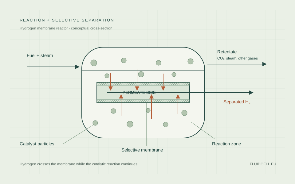
A hydrogen membrane reactor couples catalytic production with selective hydrogen removal. Its performance depends on how quickly hydrogen is produced, transported through the reacting gas, and passed through the membrane. Optimizing one of those steps while ignoring the others can leave a larger system with disappointing output. 1
The basic membrane-reactor explanation introduces reaction and separation. The engineering problem is to match those rates while maintaining temperature, mechanical integrity and a usable product pressure.
Palladium transport and the pressure driving force
Hydrogen dissociates at a palladium-based surface, dissolves in the metal and diffuses through it. On the permeate side, atoms recombine into hydrogen molecules. For a dense membrane whose transport is controlled by diffusion through the bulk metal, a simplified flux relation is:
J = (P / δ) × (√pᵣ − √pₚ)
J is the hydrogen molar flux, P is the material's hydrogen permeability, δ is selective-layer thickness, and pᵣ and pₚ are hydrogen partial pressures on the reaction and permeate sides. Using pressures in Pa, permeability in mol m⁻¹ s⁻¹ Pa⁻¹ᐟ² and thickness in m gives flux in mol m⁻² s⁻¹. This is a Sieverts-law form; it is not a universal fit for every supported membrane. 1
Surface reaction, support resistance, defects and gas-side transfer can change the observed pressure dependence. A measured "permeance" should include the equation and pressure exponent used to define it. Numbers based on different exponents have different units and cannot be compared directly.
Partial pressure is the quantity that matters. A feed containing 25% hydrogen at 10 bar has a hydrogen partial pressure of approximately 2.5 bar under an ideal-gas approximation. That differs substantially from a pure-hydrogen test at 10 bar. Total feed pressure alone cannot establish the driving force.
High pressure, vacuum and sweep gas
Increasing reaction-side pressure can support permeation, but it also changes reaction equilibria and increases pressure-rating requirements. For reactions that create more gas molecules, pressure can work against conversion in the absence of product removal. Reaction and separation effects must be assessed together.
Reducing permeate pressure increases the transport driving force. A vacuum system has an electrical duty, and the collected hydrogen may need recompression for its user. Product quality can also be affected by leaks into a low-pressure collection system.
A sweep gas lowers hydrogen partial pressure on the permeate side by dilution. The total pressure need not be low. But the outlet then contains hydrogen and the sweep component. Steam sweep can be condensed downstream; a non-condensable sweep requires a compatible end use or further separation. 2
FluidCELL investigated both vacuum and sweep arrangements. The final report explains why its prototype design favoured sweep gas and describes the integration constraints that followed. A layout choice belongs to the whole process, not just a membrane flux measurement. 5
Equilibrium shift is only one part of conversion
Removing hydrogen can drive an equilibrium-limited reforming reaction forward. A useful model still includes kinetics: catalyst activity, contact time and the rates of competing reactions. Equilibrium calculations define a reference for specified conditions; they do not predict how quickly a practical catalyst reaches that composition.
Temperature affects reaction kinetics, equilibrium and membrane permeability. The direction of an overall performance change therefore cannot be read from one property alone. Increasing temperature may increase hydrogen transport while accelerating material ageing or changing product selectivity.
For ethanol reforming, a catalyst must handle several intermediate reactions. Miyamoto and colleagues compared catalyst formulations with a Pd–Ag membrane under specified laboratory conditions. Their work is a reminder that membrane-reactor performance belongs to a catalyst–membrane combination. 3
Sizing membrane area requires local conditions
A first estimate multiplies flux by active area to obtain permeated molar flow. In an actual reactor, flux varies along the membrane because hydrogen is generated and removed, temperature can change, and the feed mixture evolves.
Using inlet hydrogen concentration over the entire membrane area can overpredict recovery. Selective removal lowers local hydrogen partial pressure, reducing the driving force farther along the flow path. A model should resolve those changes or justify a lumped approximation.
Recovery is the fraction of hydrogen in the relevant feed or generated stream that reaches the desired product. A reactor paper should state its denominator. Hydrogen yield, ethanol conversion and hydrogen recovery do not measure the same thing.
Membrane area must also be active area. Sealed ends, manifolds and inactive support regions add installed material without providing the same transport capacity. More tubes need distribution and collection systems, and unequal flow can make nominally identical membranes perform differently.
Thin films and porous supports
Reducing metal thickness shortens the hydrogen diffusion path and reduces palladium consumption. Supported membranes use a porous ceramic or metallic structure to carry mechanical loads while the thin metal film provides selectivity.
The support is not transport-free. Hydrogen has to pass through its pores, and thickness, pore structure and operating composition affect that resistance. Interlayers can improve the deposition surface or prevent interactions between a metal support and selective film, but each added layer has a role that must be measured. 1
A defect-free thin film is a manufacturing requirement. Pinhole flow can dominate the passage of contaminants even when most membrane area behaves as intended. Long tubes also need sealing methods that remain tight under pressure and repeated thermal cycling.
Material compatibility includes thermal expansion. A film, support and housing can expand by different amounts during heating. A membrane that survives a steady hot test may fail during startup or shutdown, so operating cycles belong in durability assessment.
Packed beds and fluidized beds
A packed bed is mechanically straightforward, but hydrogen must move through the bed to reach membrane surfaces. At high intrinsic membrane flux, gas-side transport can become the limiting step. Adding more active material to the membrane does not remove that bottleneck.
Fluidization can improve mixing and temperature uniformity around the membranes. It changes gas–solid contact and can reduce some transfer limitations. It also creates particle contact with the membrane and a potential erosion mechanism. Protective layers and particle selection must preserve transport as well as mechanical survival. 2
Bed design should therefore compare measured transport and durability. "Fluidized" does not mean perfectly uniform under every flow condition. Gas distribution, solids circulation and changes in particle size can affect operation.
Product purity is an installed-system result
Dense palladium's intrinsic hydrogen selectivity does not guarantee the purity leaving an installed reactor. Film defects, seals, manifolds and transient operation can introduce other gases. Species that do not permeate through intact metal can still enter through a bypass leak.
Report impurity concentrations and detection limits in addition to total hydrogen fraction. A PEM fuel cell is sensitive to particular contaminants, especially those that interfere with the anode catalyst. A concentration percentage without a species list is inadequate for judging compatibility.
Test both pure-gas transport and mixed-gas operation. Pure hydrogen establishes part of the transport behaviour. Reforming mixtures test inhibition and gas-side effects. Reactive tests include catalyst interactions and heat balance. None of those tests alone establishes years of service.
Reading claims about system efficiency
The 2017 paper on FERRET, FluidCELL and BIONICO compares system concepts and performance calculations. Its FluidCELL efficiency figures should be read with their design and simulation conditions, not as final proof that the full integrated prototype met every target. 4
The subsequent FluidCELL final report records leakage, lower-than-expected permeance and difficulty sustaining the required hydrogen output and quality during integration. It illustrates why successful component tests and a working complete system are separate milestones. 5
For an engineering comparison, include feed preparation, heat recovery, sweep or vacuum demand, compression, purification and maintenance. The relevant question is how much usable hydrogen or net electrical power the complete installation supplies, at a declared quality and energy boundary. The PSA and membrane comparison covers alternatives when separation is performed outside the reactor.
Sources & further reading
- Alique et al. (2018). Review of Supported Pd-Based Membranes Preparation by Electroless Plating for Ultra-Pure Hydrogen ProductionMembranes, 8(1), 5 · Open access, CC BY 4.0. Thin films, supports, transport and failure mechanisms.
- Recent Advances in Pd-Based Membranes for Membrane Reactors (2017)Molecules, 22(1), 51 · Open access, CC BY 4.0. Membrane transport, reactor configurations and reforming research.
- Miyamoto et al. (2016). Effects of Catalysts and Membranes on the Performance of Membrane Reactors in Steam Reforming of Ethanol at Moderate TemperatureProcesses, 4(2), 18 · Open access, CC BY 4.0. Comparison of Ni/CeO₂ and Co/CeO₂ with a Pd–Ag membrane.
- Di Marcoberardino et al. (2017). Achievements of European projects on membrane reactor for hydrogen productionJournal of Cleaner Production, 161, 1442–1450 · Design and simulation context for FERRET, FluidCELL and BIONICO; not final validation of the integrated FluidCELL system.
- FLUIDCELL: final report summaryEuropean Commission, CORDIS · Consortium-reported component tests, modelling and integration limitations.